- Executive Summary
- Introduction
- Purpose
- Scope
- Objective
- Rationale
- Need for a New Standard
- Terminology and Definitions
- Signals
- Seismological Objects and Formats
- Equipment and Hierarchical Relationship
- Proposed Event Classes
- Overview
- General Format Considerations
- Data Exchange Requirements
- Overview
- Seismic System Information Categories
- Waveforms
- Catalog
- Inventory/System Information
- Velocity Grids
- μSeismic Data Format
- Overview
- QuakeML
- Modifications
- Additional Parameters
- Event Type Mapping
- Waveforms and StationXML
- Modifications
- Parameter Validation
- Stream Naming Convention
- Grid Data Format
- Overview
- Feedback Mechanism
- Appendix A: Source Parameters
- Appendix B: Response
- Instrument Response
- IRIS NRL
- Appendix C: Coordinate System Handling
- Coordinate System Handling
Coordinates ClassCoordinateTransformation ClassCoordinateSystem Enumeration
- References
- Abbreviations Glossary
Executive Summary
This Request for Comments (RFC) proposes a standardized format for microseismic data exchange. Primarily optimized for in-mine monitoring systems, the format holds universal relevance for all microseismic data dependent on local coordinate systems.
Our objective is to simplify the exchange of microseismic data between various platforms and vendors. Presently, data conversions can undergo lossy transformations, ushering in reconciliation challenges and inconsistencies. The task of cross-referencing multiple data elements, such as event data, system information, sensor response, and waveform data, remains intricate and often ambiguous.
Central to our proposal is the exploitation of the Adaptable Seismic Data Format (ASDF), with suggested minor adjustments ensuring unchanged compatibility with other platforms. The ASDF adopts well-established file formats from seismology:
| Data Type |
Format |
| Waveform |
miniSEED-like |
| Catalog |
QuakeML |
| System Inventory |
StationXML |
Designed for extensibility, the ASDF format facilitates atomic, computationally efficient access to waveform data. This is crucial when handling vast data volumes, such as with continuous data streams or distributed acoustic sensing (DAS).
Beyond the seismic data format, our proposal extends to the definition of grid data. We present a format tailored for the storage and transfer of such data. The suggested format is versatile, accommodating various grid types including but not limited to velocity, and travel time.
The μQuake (microQuake) library serves as a practical mechanism to adopt the standards we outline in this proposal. While its foundation lies in Obspy, μQuake is tailored specifically to the nuances of microseismic monitoring. Beyond the core capabilities of Obspy, μQuake has evolved over time, with Version 2.0 poised to incorporate support for the ASDF file format and the grid structures proposed herein, ensuring a seamless integration of these new standards.
Our objective is to see a progressive adoption of the standard by the industry and the supplier and to provide a blueprint for a modern, expandable and computationally efficient data format suitable for conventional upcoming monitoring alike.
Your feedback is essential and greatly appreciated. Feedback can be provided either through the github issues associated with the RFC (RFC micro-seismic data exchange format repository on GitHub or by contacting us via email.
Introduction
Purpose
This RFC aims to invite comments on a suggested format to allow for standardized and consistent access to μseismic data collected by mine μseismic monitoring systems. The proposed conventions and format objective is to enable a seamless, lossless and convenient exchange between different platforms. It considers future needs for developing high-performance, flexible, and accurate artificial intelligence that is envisioned to use the full range of available seismic data.
Note: The objective of the proposed standard does not concern or prescribe how seismic data are internally managed within proprietary platforms, although the proposed implementation is designed for high performance and computational efficiency and would be suited for that purpose.
The proposed standard applies to triggered events and continuous recording alike, and is suited for efficiently storing the high-density DAS data.
Access to the μseismic data collected by in-mine monitoring systems is currently inconsistent. Variations arise from site to site and vendor to vendor and are often tailored to third-party requests. Such inconsistencies lead to inefficiencies, making data usage unnecessarily challenging and limiting the potential of μseismic data.
To ensure mines have access to technologies and approaches leading to optimal outcomes permitting the safe and productive operation of mines, allowing unrestricted access to μseismic data in a standardized format is a must.
This document proposes conventions and a format for the lossless and seamless exchange of μseismic data.
We want to provide a blueprint for a modern, expandable and computationally efficient data format suitable for conventional upcoming monitoring alike. The purpose is not to impose a standard but rather provide a blueprint for a modern, expandable and computationally efficient data format suitable for conventional upcoming monitoring alike.
Scope
The standard outlined in this RFC seeks to:
- Define comprehensive, flexible and extensible data formats and structure for μseismic data exchange, encapsulating all necessary data elements to foster the normalization of data processing and analysis. The proposed framework is designed to enhance interoperability between various sites and vendors, minimizing discrepancies stemming from the lack of common reference.
- Propose adaptations to the base format to capture the essence of mining data.
- Defining a list of acceptable event types in mining.
- Establishing an unequivocal and standardized naming convention for the logical organization of the seismic system components.
Objective
This RFC aims to:
- Foster a standardized representation of μseismic data, creating a universally accepted convention and eliminating fragmented or inconsistent data representations.
- Facilitate an efficient mechanism for the storage, dissemination, and accessibility of μseismic data. Ensuring versatility and catering to diverse applications ranging from real-time processing to long-term data analysis.
- Promote cross-platform compatibility, ensuring the data can be seamlessly processed, interpreted, and utilized irrespective of the platform, tool, or system.
- Enhance data integrity, ensuring it remains consistent, accurate, and unaltered during exchanges, making it reliable for various analytical and operational purposes.
Rationale
Need for a New Standard
The increase in microseismic data, particularly from expansive monitoring systems and new technologies like DAS, underscores the pressing need for an efficient and unified data format. Currently, the system information, catalog, and waveform data are provided in a series of files that do not allow simple cross-referencing. For instance, one file may refer to a sensor with a long name, whereas another uses a numerical ID. The link between the name and the numerical ID is left ambiguous. Some other essential information such as the sensor types to identify whether the sensor is a 4.5Hz or 15Hz geophone, a high-frequency accelerometer, or a low-frequency FBA.
The varied nature of microseismic data formats hinders streamlined integration and analysis, posing challenges in managing and deriving value in datasets collected by in-mine monitoring systems. The lossy and incoherent nature of current data exchange formats hinders innovation and makes the utilization of μseismic data unnecessarily tricky. Given the critical importance of microseismic data in ensuring safety and improving underground mining operations, establishing a standardized format and mechanism of exchange becomes imperative. The proposed standard objective is facilitating more straightforward data access, efficient storage, smoother data exchanges across different platforms, and accommodating various data types.
—
Terminology and Definitions
Signals
-
Trigger
Represents any type of signal, usually but not always impulsive, that “triggers” the seismic system.
-
Event
Indiscriminately, represent any association triggers occurring within a predefined time window.
-
Seismic Event (mining induced)
Usually refers to a mining induced event that results from the interaction of stress (increase or decrease) and the rock mass that can be linked to a series of phenomena including but not limited to:
-
Rock/Strain burst: The violent ejection of rock that is a primary concern in mines.
-
Slip motion (Fault slip): Movement along existing geological features.
-
Fall of ground: A broad term that effectively captures events like rock falls.
-
Tensile or compressive fracturing: The breakage of the rock as a result of compressive or tensile forces.
-
Shear rupture: A rupture along weaknesses in the rock that results in a shear motion.
-
Pillar crushing/damage: Fracturing of the rock inside a pillar, resulting in its integrity to be compromised or affected.
-
Blast (development, production, other)
Refers to a man made controlled explosion linked to the development of excavation or the extraction of ore.
-
Waveforms
A time series representation of seismic wave amplitudes detected by sensors in microseismic monitoring. Originating from subsurface events like rock fractures.
-
Catalog/Seismic Bulletin
A curated collection of detected and processed microseismic events, systematically listing key parameters such as event origin time, location, magnitude, corner frequency, and energy. Derived from waveform analysis, the catalog serves as a comprehensive record of seismicity.
-
Inventory
A structured repository detailing the metadata of seismic networks, stations, and their associated instrumentation. It encompasses station location, operational time periods, instrument response, and channel configurations.
-
SEED
A standardized format for representing and exchanging digital seismological data encompassing waveform records and related metadata. Established by the Federation of Digital Seismographic Networks (FDSN), SEED (Standard for the Exchange of Earthquake Data) is widely adopted for its ability to consolidate seismic data and its associated station and instrument information into a unified structure, ensuring consistency and interoperability in seismological research and monitoring.
-
MiniSEED
A subset of the SEED format specifically designed for the exchange and storage of seismic waveform data. While the broader SEED standard encompasses data and comprehensive metadata, MiniSEED focuses solely on time series data, making it more compact and suitable for efficient data transmission and storage. Despite its simplicity, MiniSEED retains the essential headers for data identification and integrity, ensuring its applicability in diverse seismological applications.
-
QuakeML
A standardized XML-based data format developed for representing and exchanging seismological data related to earthquakes. By covering event parameters like origins, magnitudes, and phase picks, QuakeML aims to facilitate interoperability and consistency in sharing and processing seismic event information across various seismological tools and platforms. Its structured schema ensures that earthquake-related data are described comprehensively yet flexibly, catering to diverse seismological research and monitoring needs.
-
StationXML
A modern XML-based format designed for the representation and exchange of metadata associated with seismic stations, networks, and associated instruments. Evolved as a successor to the SEED format’s metadata component, StationXML provides a detailed description of station configurations, instrument response information, and operational time periods, among other attributes. Its structured framework ensures a comprehensive and consistent portrayal of the seismic data acquisition chain, promoting accurate data interpretation and seamless exchange across seismological applications.
-
HDF5 (Hierarchical Data Format version 5)
An advanced data model, library, and file format designed for storing and organizing large volumes of complex data, including arrays of numbers, multidimensional datasets, and metadata. HDF5 is optimized for high performance and flexibility, allowing for efficient storage and retrieval across diverse platforms and languages. Its hierarchical structure supports grouping related objects and tagging with rich metadata, making it a widely adopted choice for scientific computing applications where complex datasets and their associated metadata need to be integrated.
-
ASDF (Adaptable Seismic Data Format)
A modern data format explicitly designed for seismological data and related metadata. Building on the HDF5 infrastructure, ASDF is tailored for efficiency, scalability, and adaptability in both storage and processing of seismic data. It facilitates the integration of raw waveforms, processed data products, event parameters, and station metadata within a single file structure. The format’s adaptability and hierarchical structure ensure consistent and optimized handling of diverse seismic datasets, making it a valuable choice for advanced seismological research and applications.
Equipment and Hierarchical Relationship
The suggested hierarchy deviates from the standard Obspy/StationXML definition. We suggest some small amendments that do not infer with the compatibility but provide a logical way to organize the Equipment or inventory in a microseismic monitoring system.
Inventory
- Definition: The collective framework that encapsulates all networks within a microseismic monitoring system.
Network (e.g., N1)
- Definition: A two-character code that aggregates several stations for the purpose of seismic event detection, location, and characterization.
- Relation: Top-level entity within the Inventory.
Station (e.g., N1.STA01)
- Definition: A logical identifier with five characters for a set of instruments at one or more defined locations to capture seismic data.
- Relation: Constituent of a Network.
Location (e.g., N1.STA01.00)
- Definition: A geospatial identifier with two characters, equivalent to the physical installation point of an Instrument.
- Relation: Component of a Station.
Instrument
- Definition: The physical equipment installed at a Location, potentially inclusive of multiple sensors and their ancillary components for seismic signal capture.
- Correspondence: Directly associated with a Location, not a hierarchical dependency.
Channel (e.g., N1.STA01.00.GNX)
- Definition: A three-character designation for a data stream from a sensor, indicative of its bandwidth, type, and orientation.
- Correspondence: Specifically linked to a single Sensor type within an Instrument.
Sensor (e.g., Sensor - Type 1)
- Definition: A device engineered to detect seismic waves and transduce them into a measurable electrical signal, with a distinct type for each Channel.
- Correspondence: Each Sensor is uniquely coupled with a Channel; they are mutually inclusive.
Hierarchy
Inventory
|
|-- Network (N1)
|   |
|   |-- Station (N1.STA01)
|   |   |
|   |   |-- Location: Instrument (N1.STA01.00)
|   |       |
|   |       |-- Channel (N1.STA01.00.GNX)
|   |       |   |
|   |       |   |-- Sensor - Type 1
|   |       |
|   |       |-- Channel (N1.STA01.00.GNY)
|   |       |   |
|   |       |   |-- Sensor - Type 2
|   |       |
|   |       |-- Channel (N1.STA01.00.GNZ)
|   |           |
|   |           |-- Sensor - Type 3
|   |
|   |-- Station (N1.STA02)
|   |   |
|   |   |-- (similar structure as N1.STA01)
|   |
|   |-- (Additional stations with unique codes)
|
|-- Network (N2)
|   |
|   |-- (similar structure as Network N1)
|
|-- (Additional networks with unique codes)
Stream (Stream identifier): A stream uniquely relates to a source of data. The stream id uniquely identifies the data provenance. A stream identifier is composed by combining the network, station, location and channel code in one string. An example of a stream id is NETWORK.STATION.LOCATION.CHANNEL.
Proposed Event Classes
Overview
Uniformity and portability can only be achieved if the event classification is constrained to a series of classes broad enough to encompass most situation and event types encountered, but not so large that it become ambiguous.
If simplicity is the objective, the classification could be limited to the following three generic categories:
- seismic event;
- blast; and
- noise.
That would, however, be too reductionist and lead to ambiguity. The list suggested below is quite comprehensive, and from experience, encompass almost all event types that can be recorded by a mine μseismic monitoring system.
Seismic Event
| Suggested Event Types |
Description |
| seismic event |
Generic Mining induced seismic event* |
| earthquake/large event |
Tectonic earthquake or very large events recorded by national seismograph network |
| offsite event |
Used for a seismic event happening at, for instance, a nearby operation |
| rock burst |
Sudden and violent release of built-up stress within the rock. |
| fall of ground/rockfall |
Dislodgement and downward movement of rock or ground. |
Blast
| Suggested Event Types |
Description |
| blast |
Generic Blast: Controlled detonation for mining purposes. |
| blast sequence |
Would apply for a series of blasts organized in a longer file containing the whole blast sequence. |
| development blast |
Specific type of blast for development |
| production blast |
Specific type of blast related to production |
| far away blast/open pit blast |
Detonation outside underground mine, often in open pit operations or nearby quarry. |
| offsite blast |
Controlled explosion occurring outside the mine’s premises. |
| paste firing |
Detonation within cemented paste backfills. |
| calibration blast |
Detonation to calibrate or test seismic monitoring equipment. |
| other blast/slashing |
Miscellaneous detonations not fitting standard categories. |
| mid-shift blast/slash blast |
Detonation conducted during a shift change or mid-shift. |
Noise
| Suggested Event Types |
Description |
| noise |
Generic Noise/ Unknown |
| crusher noise |
Sound from machinery crushing ore or rock. |
| orepass noise |
Sound originating from ore movement in passes or chutes. |
| drilling noise |
Acoustic disturbance from drilling activities. |
| electrical noise |
Interference from electrical sources or equipment. |
| scaling noise |
Noise associated with removal of loose rock from mine walls or roof. |
| mechanical noise |
Sound from general mechanical operations or machinery. |
| test pulse |
Controlled signal used to test or calibrate seismic equipment. |
| unidentified noise/other noise |
Acoustic disturbances without clear origin or classification. |
| raise bore |
Mechanical method for drilling between levels in mines. |
Other
| Suggested Event Types |
Description |
| duplicate |
Event already recorded or identified; redundant entry. |
| tap test/test |
Controlled tapping or impact to test response of monitoring systems usually done during the installation and commissioning of the system to test the equipment. |
This section delves into the overarching design principles and foundational elements underpinning the proposed format, ensuring adherence to the objectives of seamless, lossless, and convenient data interchange across platforms.
-
Data Integrity and Consistency: Details on mechanisms, potentially including checksums, versioning, or other measures, to ensure data remains unaltered and consistent during transfers.
-
Platform Independence: Insights into how the format maintains neutrality to specific proprietary platforms, endorsing cross-platform compatibility.
-
Scalability and Flexibility: Addressing the format’s ability to manage both small and expansive datasets, e.g., high-density DAS (Distributed Acoustic Sensing) data.
-
Usability: Features enhancing the user-friendliness of the format, which may encompass aspects like readability, annotations, or metadata.
-
Efficiency: Discussion around computational considerations, ensuring both data storage and exchange remain efficient.
-
Extensibility: Considerations on the format’s design, allowing it to evolve and accommodate future technological shifts or data needs.
-
Standardized References: Incorporating standardized naming conventions, directory structures, and file naming conventions.
-
Interoperability with Existing Formats: Examination of the format’s relationship or interaction with prevailing data formats in the domain.
—
Data Exchange Requirements
Overview
The intended application directly governs the specificity of data requirements. When catalog data meets quality standards and its classification, location, and source parameters are reliable, it may suffice for certain applications. However, for more demanding or complex tasks, raw waveforms and accompanying metadata become essential. Sole reliance on catalog data in such instances often leads to ill-posed problems characterized by insufficient model space orthogonality and ambiguous solutions. To fully leverage waveform data, access to inventory or system metadata is imperative for instrument localization and sensor characterization. For completeness, one could also benefit from access to seismic velocities, especially when 3D models are used.
Seismic system information can be partitioned into four main categories:
-
Catalog: Catalog data includes processed attributes related to seismic events: time, location, magnitude, amplitude (PPV, PPA), classification, P- and S-wave picks, and moment tensor/focal mechanism data.
-
Inventory: Details the seismic network, stations, and sensor configurations. This includes sensor location, type, response, and orientations. Inventory data should facilitate necessary data manipulation for analysis.
-
Waveform: Raw or event-triggered time-series data recorded by the instruments, foundational for all seismic analyses.
-
Velocities/Travel Time Grids: Required for location, magnitude calculation, and moment tensor inversion. Allows for ray tracing and wavefield rotation to isolate P- and S-waves.
Information in these categories must be internally coherent, enabling straightforward cross-referencing and understanding of data provenance and relationships.
Waveforms should include:
- Instrument and channel ID
- Sampling rate or interval
- Start time
- Amplitude, in ADC counts or physical units
Catalog
Catalog data is bifurcated into:
- Event-related: Minimum requirements:
- Time (local and UTC)
- Location
- Classification
- Magnitude, along with seismic moment $M_0$ and corner frequency $f_c$ for moment magnitude
- Radiated energy for P- and S-waves
- Moment tensor solution if available
- Waveform-related: Derived from waveform data:
- Picks: P- and S-wave onset times
- Amplitude: Information, evaluation mode, and status
Minimum inventory requirements:
- Instrument ID
- Location
- Channel orientations
- Instrument response, per channel
Velocity Grids
A functional velocity grid should comprise:
- Origin
- Spacing between grid nodes
- Dimensions: Number of grid points in each axis
- Data: Grid values
- Units (m or ft)
—
Overview
The recommended seismic data standard for adoption is the Adaptable Seismic Data Format (ASDF) [Krischer et al., 2016]. Designed with modern challenges in mind, the ASDF format efficiently addresses the complexities inherent to large and detailed seismic datasets. By employing the Hierarchical Data Format Version 5 (HDF5) container format, ASDF is self-descriptive, ensuring data can be accessed and manipulated with ease across various seismological applications. Its overarching objective is to simplify the organization and exchange of seismic data, emphasizing interoperability, scalability, and the reduction of inconsistencies by amalgamating multiple seismic data components within a singular structure. The ASDF format is suitable for trigger, continuous, and Distributed Acoustic Sensing (DAS) data to name only those.
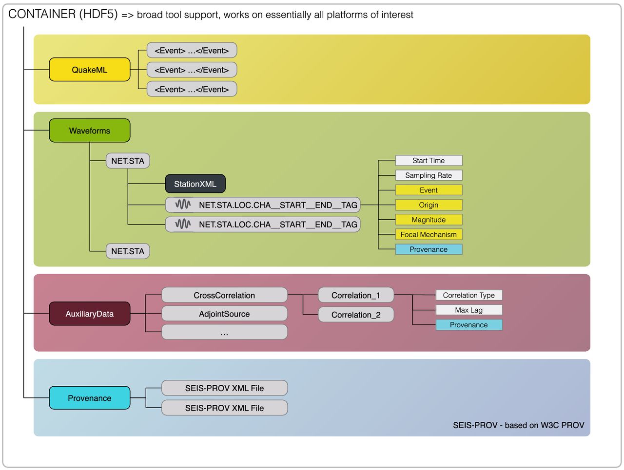
*Figure: ASDF data structure overview (Krischer et al. 2016)
Nested within the HDF5 container, ASDF systematically organizes seismological components, including:
-
QuakeML: An XML-based language, QuakeML focuses on event metadata, cataloging seismic event descriptions such as event origins, magnitudes, and moment tensor solutions.
-
Waveform Data: The heart of the ASDF, this section contains time series representations of seismic waveforms. In the ASDF format, waveform data are exclusively represented using single and double-precision floating point values, or signed integers. These representations are encapsulated as native data arrays within the HDF5 framework.
-
StationXML: Serving as a repository for station metadata, this section contains detailed instrument information, including their responses, station coordinates, and other specific attributes. This metadata provides vital context to the waveforms. In the ASDF format, this inventory information is appended directly to the waveforms at the station level.
-
Auxiliary Data: Catering to the diverse needs of seismological analyses, this section allows the storage of additional data types, such as cross-correlations or synthetic seismograms.
-
Provenance Data: In the pursuit of rigorous transparency and reproducibility, this segment meticulously documents the historical progression of data alterations, enumerating each distinct processing operation along with its respective parameters. The provenance documentation adheres to the W3C PROV model [Moreau et al., 2013], a widely accepted standard for chronicling provenance specifics.
Through its comprehensive integration of these components, ASDF paves the way for a standardized, efficient, and in-depth approach to seismological research and data management.
While the ASDF format provides a robust framework for general seismic data handling, specific adaptations are imperative to address the unique requirements of μseismic monitoring within mining environments. The proposed changes leverage the inherent flexibility and expandability of the QuakeML and StationXML formats.
Note: Coordinate Systems:
Utilizing a Cartesian coordinate system (x, y, z) introduces inherent ambiguities. We recommend imposing constraints on the alignment of the x, y, and z axes to ensure the coordinate system is right-handed and aligned with geographical axes. Specifically, we advocate the use of ENU and NED coordinate systems.
μquake version 2.0 introduces the Coordinates Class. The handling is done by converting the Coordinate object to JSON and writing the JSON string as an object extra parameters.
<?xml version='1.0' encoding='utf-8'?>
    <q:quakeml xmlns:mq="https://microquake.ai/xml/event/1"
    xmlns="http://quakeml.org/xmlns/bed/1.2"
    xmlns:q="http://quakeml.org/xmlns/quakeml/1.2">
**Note: Provenance and Auxiliary Data
The ASDF format implementation of the provenance information and the extensibility through the use of the auxiliary data allows for the file format to 1) allow to rigourously trace the steps taken in transforming the data and 2) provides convenient and robust mean of future proofing the data format so additional information can be added in the future withouth breaking the compatibility. However, this standard is currently not prescribing the use of provenance data and is not making use of the auxiliary block. The proposed standard, for historical reasons rooted in previous implementation, instead exploits the inherent extensibility of the QuakeML and StationXML through namespaces.
The modifications discussed in the following sections, particularly concerning QuakeML and StationXML formats, have been operationalized in the μquake library. This library extends the Obspy package and is tailored to the specific needs of μseismic monitoring within the mining contexts.
QuakeML
Modifications
Additional Parameters
| Object |
New Parameter |
Description |
Type |
| Origin |
coordinates |
Coordinates information |
Coordinates |
| Magnitude |
$f_0$ |
Corner frequency |
float |
| |
$E_p$ |
P-wave energy |
float |
| |
$E_s$ |
S-wave energy |
float |
We propose straightforward modifications to the QuakeML format to better suit museismic applications. The first concerns the expression of coordinates using the Cartesian system previously described instead of the longitude, latitude, and depth/elevation. The second pertains to expanding the Magnitude object definition to include the corner frequency and the P- and S-wave energies. The third involves the overriding of event types.
Instead of the standard spherical coordinate system that relies on latitude and longitude for location specification, we advocate for a Cartesian coordinate system. Specifically, we recommend emptying the traditional fields for latitude, longitude, elevation, and depth. As a substitute, we propose adding a description of the Coordinates as a new field. The coordinate description object is implemented in $\mu$Quake from version 2.0. In the current implementation, the information is stored as a JSON string in the extra parameters of the Origin object. The extra parameters are then stored in a specific namespace inside the QuakeML file. The coordinate object includes the x, y, and z coordinate, a description of the coordinate system (either ENU or NED), and elements to allow for converting the coordinates between multiple representations including latitude, longitude if the required information is provided.
We propose an enhancement to the Magnitude definition in QuakeML to represent seismic source properties better. The existing schema falls short in capturing key parameters such as the corner frequency ($f_0$), and the P- and S-wave energies $E_p$ and $E_s$, respectively). Similar to our approach for coordinate system modification, we suggest including $f_0$, $E_p$, and $E_s$ as extra parameters of the Magnitude object. This enables the on-the-fly calculation of other source parameters using the seismic moment $M_0$, corner frequency, and wave energies. Relationships among these source parameters are elaborated in Appendix.
Event Type Mapping
Transitioning to event classifications, the QuakeML schema has a predefined set of seismic event types that do not fully accommodate the specialized needs of μseismic monitoring. We propose mapping existing event types to new, mining-specific descriptors and directly including a generic look-up table in the code for on-the-fly translation. While efforts were made to create logical mappings, limitations in the existing event types posed challenges in finding intuitive counterparts. The following table presents this mapping between standard and μseismic event types.
Seismic Event
| Event Type (mining) |
Event Type (QuakeML) |
| seismic event |
induced or triggered event |
| earthquake/large event |
earthquake |
| offsite event |
atmospheric event |
| rock burst |
rock burst |
| fall of ground/rockfall |
cavity collapse |
Blast
| Event Type (mining) |
Event Type (QuakeML) |
| blast |
explosion |
| blast sequence |
accidental explosion |
| development blast |
industrial explosion |
| production blast |
mining explosion |
| far away blast/open pit blast |
quarry blast |
| offsite blast |
nuclear explosion |
| paste firing |
chemical explosion |
| calibration blast |
controlled explosion |
| other blast/slashing |
experimental explosion |
| mid-shift blast/slash blast |
industrial explosion |
Noise
| Event Type (mining) |
Event Type (QuakeML) |
| noise - Generic Unknown |
other event |
| raise bore |
hydroacoustic event |
| crusher noise |
road cut |
| orepass noise |
collapse |
| drilling noise |
acoustic noise |
| electrical noise |
thunder |
| scaling noise |
anthropogenic event |
| mechanical noise |
crash |
| test pulse |
sonic boom |
Other
| Event Type (mining) |
Event Type (QuakeML) |
| duplicate |
boat crash |
| unknown |
plane crash |
| tap test/test |
avalanche |
Note: The above mapping is implemented in the uQuake library to allow for seemless mapping of the uQuakeML and QuakeML types.
Modifications
| Object |
New Parameter |
Description |
Type |
| Network |
Time Zone |
IANA Time Zone or time offset |
string |
| Station |
coordinates |
Coordinates information |
coordinates |
| Channel |
coordinates |
Coordinates information |
float |
| |
oriented |
True if orientation is known |
boolean |
| |
active |
True if the channel is active |
boolean |
In a manner analogous to our QuakeML modifications, we adapt the StationXML format to meet the specific needs of the μseismic context. The changes affect the Network, Station, and Channel definitions. Support for a local coordinate system is added to the Station and Channel definitions, and two new parameters are introduced in the Channel definition to indicate orientation and current activity status. The mutable ‘active’ flag allows for the temporary exclusion of a component due to timing issues or other transient problems. These changes include support of the Coordinates object in the Station and Channel objects, and the storage of the Coordinates as JSON string as extra parameters. Time zone information is added to the Network definition to facilitate conversion between local and UTC time. The provided time zone must either represent an offset from Coordinated Universal Time (UTC) or correspond to a valid entry in the IANA time zone database. The μquake library ensures seamless integration of these modifications and replicates Obspy’s default behavior regarding location data. It also allows the extraction of predefined values from the extra parameters section as typical object properties.
The waveform format does not require any alteration.
Parameter Validation
As for the QuakeML, the validation for the newly introduced parameters is performed within the μquake library. For standard parameters, validation is handled by the Obspy package. This ensures a cohesive framework for both standard and specialized seismic data types.
Stream Naming Convention
The ASDF file format combines waveforms and inventory data. To ensure flawless integration, we must adopt a robust and standardized “stream” naming convention to ensure unambiguous association between waveforms and inventory.
ASDF adopts a relaxed version of the SEED Identifier Convention, previously part of QuakeML and StationXML standards and now extended to the waveform data. The StationXML does not restrict the string length; QuakeML does. We therefore suggest adopting the convention presented in section 3.3.5 of the QuakeML Version 1.2 (revision 20130214b).
Overview
The HDF5 format serves as a robust and scalable data storage platform optimized for handling complex and large datasets. In the realm of microseismic monitoring, the format’s hierarchical file architecture, akin to a file system, proves invaluable for organizing grid data and associated metadata efficiently.
Two primary categories of grids are relevant:
- Global: These grids extend across the entire network, typical examples being P- and S-wave velocity grids.
- Instrument Specific: These grids are confined to individual instruments and are typically used for storing travel time and angle information.
Velocity Grid
/Phase {P or S} for Velocity Grid and InstrumentID for travel time
    @Grid ID (Attribute, type: string)
    @Schema Version (Attribute, type: string)
    @Creation Timestamp (Attribute, type: string - ISO 8601 format)
    @Type (Attribute, type: string - value from the set {'VELOCITY'})
    @Units (Attribute, type: string - value from the set {'m/s', 'ft/s', 's/m', 'ft/s'})
    @Coordinate System (Attribute, type: string - reference to coordinate system used)
    @Origin (Attribute, type: float[3])
    @Spacing (Attribute, type: float[3])
    @Dimensions (Attribute, type: int[3])
    @Compression (Attribute, type: string - description of any compression used)
    /Data (Dataset, type: float[n, m, l], optional: checksum)
The structure accommodates both a single and multiple phase.
Instrument Grids (Velocity, Angles)
For instrument-specific grids, the structure is proposed to be:
/Phase {P or S} (Group)
	/InstrumentID (Group)
		/Grid Type ('TIME', 'AZIMUTH', 'TAKEOFF', ...)
		    @Grid ID (Attribute, type: string)
		    @Seed Station Code (Attribute, type: str)
		    @Seed Location Code (Attribute, type: str)
		    @Seed Coordinate System (Attribute, type: str)
		    @Seed Coordinates (Attribute type: float[3])
		    @Schema Version (Attribute, type: string
		    @Velocity Model ID (Attribute, type: string)
		    @Modification Timestamp (Attribute, type: string - ISO 8601 format)
		    @Type (Attribute, type: string - value from the set {'TIME', 'ANGLE'})
		    @Units (Attribute, type: string - value from the set {'SECOND', 'DEGREES'})
		    @Coordinate System (Attribute, type: string - reference to coordinate system used)
		    @Origin (Attribute, type: float[3])
		    @Spacing (Attribute, type: float[3])
		    @Dimensions (Attribute, type: int[3])
		    @Compression (Attribute, type: string - description of any compression used)
		    /Data (Dataset, type: float[n, m, l], optional: checksum)
Note: The only difference between the global (Velocity) and instrument specific grid definition is that for instrument grid, additional parameters are added to ensure cross-referencing to a velocity grid (Velocity Model ID) and that the Seed information is preserved (Seed Station, Seed Location, Seed Coordinate System, Seed Coordinates).
Feedback Mechanism
Feedback and contributions from the community are essential to refining and improving this RFC. There are two primary ways through which stakeholders, developers, and interested parties can provide their feedback:
-
GitHub Issues:
- Navigate to the RFC micro-seismic data exchange format repository on GitHub.
- Go to the
Issues tab.
- Click on
New Issue to create a new issue.
- Provide a concise title and detailed description of your feedback, suggestions, or concerns.
- Once submitted, the issue will be visible to the community, and the project maintainers will review and address it as appropriate.
-
Email:
- If you prefer a more direct approach or have feedback that you’d like to keep private, you can email rfc_format@microquake.ai.
- Please provide a clear subject line relevant to your feedback to ensure swift handling of your email.
- While we appreciate all feedback, do note that due to the volume of emails, it might take some time before you receive a response.
Whether you choose to leave an issue on GitHub or send an email, your feedback is invaluable. It aids in ensuring that the proposed micro-seismic data exchange format is robust, relevant, and addresses the needs of the community.
Thank you for taking the time to review this RFC and for your contributions towards its continual improvement.
—
style: default
—
Appendix A: Source Parameters
In this appendix, we outline the equations that relate the core canonical source parameters — Seismic Moment $M_0$, Corner Frequency, $f_0$ and the P- and S-wave Energies $E_p$ and $E_s$ — to the derived source parameters commonly used in microseismic studies.
| Derived Parameter |
Equation |
| Moment Magnitude |
$M_w = \frac{2}{3} \left( \log_{10} M_0 - 9.1 \right)$ |
| Radiated Energy (J) |
$E = E_p + E_s$ |
| Source Radius (m) |
$a = \frac{c \cdot v}{f_c}$ |
| Rupture Area (m^2) |
$\pi a^2$ |
| Potency (m^3) |
$P = \frac{M_0}{\mu}$ |
| Apparent Stress (Pa) |
$\sigma_a = 2 \cdot \frac{E}{P}$ |
| Apparent Volume (m^3) |
$\frac{M_0^2}{\mu \cdot E}$ |
| Static Stress Drop (Pa) |
$\Delta\sigma = \frac{7}{16} \cdot \frac{10^{\left(\frac{3}{2} M_w + 9.1\right)}}{\left(a \right)^3}$ |
Note: Where $\rho$ is the density, $V_p$ and $V_s$ are the P- and S-wave velocities expressed in m/s, $\mu$ is the shear modulus, and $Y$ the Young modulus. $c$ is a scaling constant that depends on the source model. For instance:
- For Brune’s model, $c=0.375$
- For Madariaga’s model
- $c=0.32$ for the P-wave; and
- $c=0.21$ for the S-wave.
—
Appendix B: Response
Instrument Response
The instrument response is a comprehensive representation of the signal transformation across the entire seismic data acquisition chain. It outlines how the original ground motion gets converted into the digital data recorded. In the SEED and Obspy frameworks, the instrument response is structured in a chain-like manner, connecting various stages such as the sensor response, pre-amplifiers, filters, and digitizers. Each stage contributes its frequency-dependent correction factors to the overall instrument response, which are often characterized by poles and zeros in the Laplace domain. By chaining these components together, one can obtain the complete response function that allows for precise ground-motion reconstruction from the recorded data.
The following example demonstrates how to construct a response for a 15 Hz geophone element connected to a 24-bit digitizer. The data are assumed to be recorded between $\pm 2.5$ volts and stored as ADC counts. We utilize the $\mu$quake library, an extension of the Obspy library specifically tailored for $\mu$seismic applications. The example includes code to create a synthetic stream with random values to simulate waveform data. Subsequently, it illustrates how to change the waveform representation from ADC counts to acceleration, velocity, and displacement.
import numpy as np
from uquake.core import Stream, Trace, UTCDateTime
from uquake.core.inventory import Inventory, Network, Station, Channel, Site
from uquake.core.inventory.response import Response, PolesZerosResponseStage, CoefficientsTypeResponseStage

# Create Inventory, Network, and Station as before
inv = Inventory(networks=[], source="Example")
net = Network(code="XX", stations=[], description="Example Network")
sta = Station(code="STA1", x=0.0, y=0.0, z=0.0, site=Site(name="Example Site"))

# Create the Channel and Response objects
cha = Channel(code="HHZ", location_code="", x=0.0, y=0.0, z=0.0, sample_rate=100.0)
resp = Response()

# Poles and Zeros for 15 Hz geophone
pz_stage = PolesZerosResponseStage(
    stage_sequence_number=1,
    stage_gain=1.0,
    stage_gain_frequency=1.0,
    input_units="M/S",
    output_units="V",
    pz_transfer_function_type="LAPLACE (RADIANS/SECOND)",
    normalization_frequency=1.0,
    zeros=[0j],
    poles=[-94.44j, 94.44j],
    normalization_factor=1.0
)

# Coefficients for 24-bit digitizer
coeff_stage = CoefficientsTypeResponseStage(
    stage_sequence_number=2,
    stage_gain=1 / (2.5 / (2**23)),
    stage_gain_frequency=1.0,
    input_units="V",
    output_units="COUNT",
    cf_transfer_function_type="DIGITAL",
    numerator=[1.0],
    denominator=[]
)

# Add stages and complete the hierarchy
resp.response_stages.append(pz_stage)
resp.response_stages.append(coeff_stage)
cha.response = resp
sta.channels.append(cha)
net.stations.append(sta)
inv.networks.append(net)

# Create a Stream with random ADC count values simulating the data
npts = 1000
starttime = UTCDateTime(0)
sampling_rate = 100.0

# Create a single Trace object
trace = Trace(data=np.random.randint(-2**23, 2**23, npts))
trace.stats.starttime = starttime
trace.stats.sampling_rate = sampling_rate
trace.stats.network = "XX"
trace.stats.station = "STA1"
trace.stats.channel = "HHZ"

# Create a Stream object and append the Trace
stream = Stream(traces=[trace])

# Attach the response to the Stream
stream.attach_response(inv)

# Convert waveform from ADC count to physical units
stream.remove_response(output="ACC")
stream.remove_response(output="VEL")
stream.remove_response(output="DISP")
IRIS NRL
The Incorporated Research Institutions for Seismology Nominal Response Library (NRL) serves as a centralized repository for sensor and digitizer responses. Inclusion of the equipment utilized in microseismic monitoring within the NRL not only guarantees the accuracy of response characteristics but also promotes standardization across platforms. This is essential for ensuring data integrity and facilitating data interchange within the broader seismic research community. Both the µquake and Obspy libraries provide mechanisms to easily integrate these NRL-specified responses into the StationXML format, thus enhancing both data fidelity and workflow efficiency.
# Using uquake
from uquake.core.inventory import Inventory, Network, Station, Channel, Site
from uquake.clients.nrl import NRL

# Initialize NRL client
nrl = NRL()

# Construct response from NRL
response_uquake = nrl.get_response(
    sensor_keys=['Sensor Manufacturer', 'Sensor Model'],
    datalogger_keys=['Datalogger Manufacturer', 'Datalogger Model']
)

# Define channel with x, y, z coordinates
channel = Channel(
    code="EHZ",
    location_code="",
    x=0.0,
    y=0.0,
    z=0.0,
    response=response_uquake
)
Appendix C: Coordinate System Handling
Coordinate System Handling
From version 2.2.0, µquake includes classes for handling coordinates and their transformations. The main classes are Coordinates, CoordinateTransformation, and CoordinateSystem. Those classes are used to describe coordinates and have been integrated in the following classes:
uquake.core.event.Originuquake.core.inventory.Stationuquake.core.inventory.Channeluquake.grid.base.Grid
Coordinates Class
The Coordinates class represents a point in a specific coordinate system. It contains the following attributes and methods:
- x, y, z: float - Coordinates in the chosen system.
- coordinate_system: CoordinateSystem - Specifies whether the system is
NED or ENU.
- transformation: CoordinateTransformation - Object for handling coordinate transformations.
The CoordinateTransformation class handles transformations between custom coordinate systems and latitude-longitude-based systems. Attributes include:
- translation: tuple - Translation vector as (dx, dy, dz).
- rotation: list or tuple - Rotation matrix or Euler angles.
- epsg_code: int - EPSG code for the target coordinate system.
- scaling: float or tuple - Optional scaling factors.
- reference_elevation: float - Reference elevation for depth conversions.
CoordinateSystem Enumeration
The CoordinateSystem enumeration specifies the coordinate system being used. It enforces a right-hand coordinate system and supports two types:
- NED - North, East, Down coordinate system.
- ENU - East, North, Up coordinate system.
References
- Krischer, L., Smith, J. A., Lei, W., Lefebvre, M., Ruan, Y., de Andrade, E. S., … & Tromp, J. (2016). An Adaptable Seismic Data Format. Geophysical Journal International, 207(2), 1003-1011.
- Moreau, L., Missier, P., Belhajjame, K., B’Far, R., Cheney, J., Coppens, S., … & Groth, P. (2013). PROV-DM: The PROV Data Model. W3C Recommendation, 30.
- FDSN. (2016). StationXML Manual. Version 1.1.
- Euchner, F., Heinloo, A., Kästli, P., Saul, J., & Weber, B. (2011). QuakeML: An XML Schema for Seismology. Version 1.2.
Abbreviations Glossary
- DAS: Distributed Acoustic Sensing
- AI: Artificial Intelligence
- FBA: Force Balance Accelerometer
- HDF5: Hierarchical Data Format Version 5
- ASDF: Adaptable Seismic Data Format
- SEED: Standard for the Exchange of Earthquake Data
- UTC: Coordinated Universal Time
- NRL: Nominal Response Library
- SMTI: Seismic Moment Tensor Inversion
- PPV: Peak Particle Velocity
- PPA: Peak Particle Acceleration
- NED: North East Down
- ENU: East North Up